Hardware
| Component | Part | Role |
|---|---|---|
| MCU | nRF52810-QCxx (QFN, marking N52810 QDAAE0) | BLE SoC, Cortex-M4 |
| IMU | LSM6DSL | 3-axis accel + gyro (motion input) |
| External flash | Macronix MX25R8035F (SPI NOR, 8 Mbit / 1 MB) | external storage |
| Clock | 32.000 MHz crystal | |
| Other | BLE antenna, LED, button |
The LSM6DSL accelerometer/gyroscope is the part this project cares about — see IMU streaming for reading it live over BLE.
IMU axis orientation
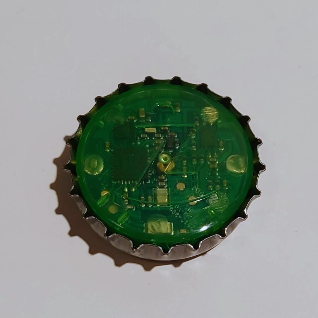
The IMU axes were mapped empirically — holding the token still in each face-up / edge-up pose and reading which accelerometer axis settles at ±1 g. Reference frame: look at the PCB face (the green board with the Ż logo) held upright; +Z points out of the PCB face, toward you.
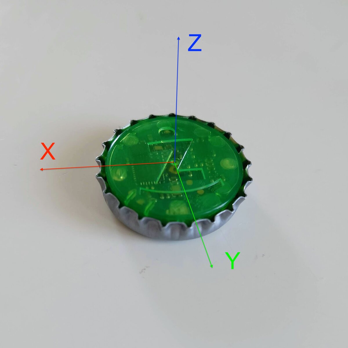
| Axis | Points toward (PCB face up, Ż upright) |
|---|---|
| +Z | out of the PCB face (Ż side) |
| −Z | out of the cap face (metal crown / "T" logo) |
| −Y | top of the Ż (12 o'clock) |
| +Y | bottom of the Ż (6 o'clock) |
| −X | right of the Ż (3 o'clock) |
| +X | left of the Ż (9 o'clock) |
The accelerometer axes form a right-handed triad (X × Y = +Z), matching the LSM6DSL convention.
Measured (token still, one axis up at a time): PCB face up → Z ≈ +1.0 g; cap face up → Z ≈ −1.0 g; top of Ż up → Y ≈ −1.0 g; right of Ż up → X ≈ −1.0 g; left of Ż up → X ≈ +1.0 g. Per-axis magnitudes vary by a few percent (uncalibrated MEMS offset/scale).
What the accelerometer vector means
The accelerometer measures specific force — the support/reaction force on the sensor — not gravity directly. At rest it reads the reaction that holds the token out of free fall, so the vector points up, away from Earth, with magnitude ≈ 1 g: the axis facing the sky reads +1 g. The direction toward Earth is therefore −accel while the token is still. In free fall it would read ≈ 0. During motion, linear acceleration adds to the gravity component — which is why orientation is recovered with a fusion filter (Madgwick) rather than by trusting raw accel as "down".